
Harmonic Analysis for Utility-Scale Power Systems: When and Why It’s Needed
If your interconnection application was ever kicked back for exceeding a utility’s harmonic distortion limits, or a capacitor bank at your facility failed months after commissioning for no obvious reason, you already know the cost of skipping harmonic analysis power systems studies. It’s one of the least understood and most consequential studies in a utility-scale project’s technical package.
Unlike load flow or short circuit analysis, harmonic distortion doesn’t show up on a single-line diagram. It hides inside inverter switching, transformer saturation, and cable capacitance, and it only becomes visible when equipment starts overheating, tripping, or failing prematurely.
This guide explains what harmonic analysis actually evaluates, the project triggers that make it mandatory, and how to avoid the interconnection delays and equipment damage that result from skipping it.
What Is Harmonic Analysis?
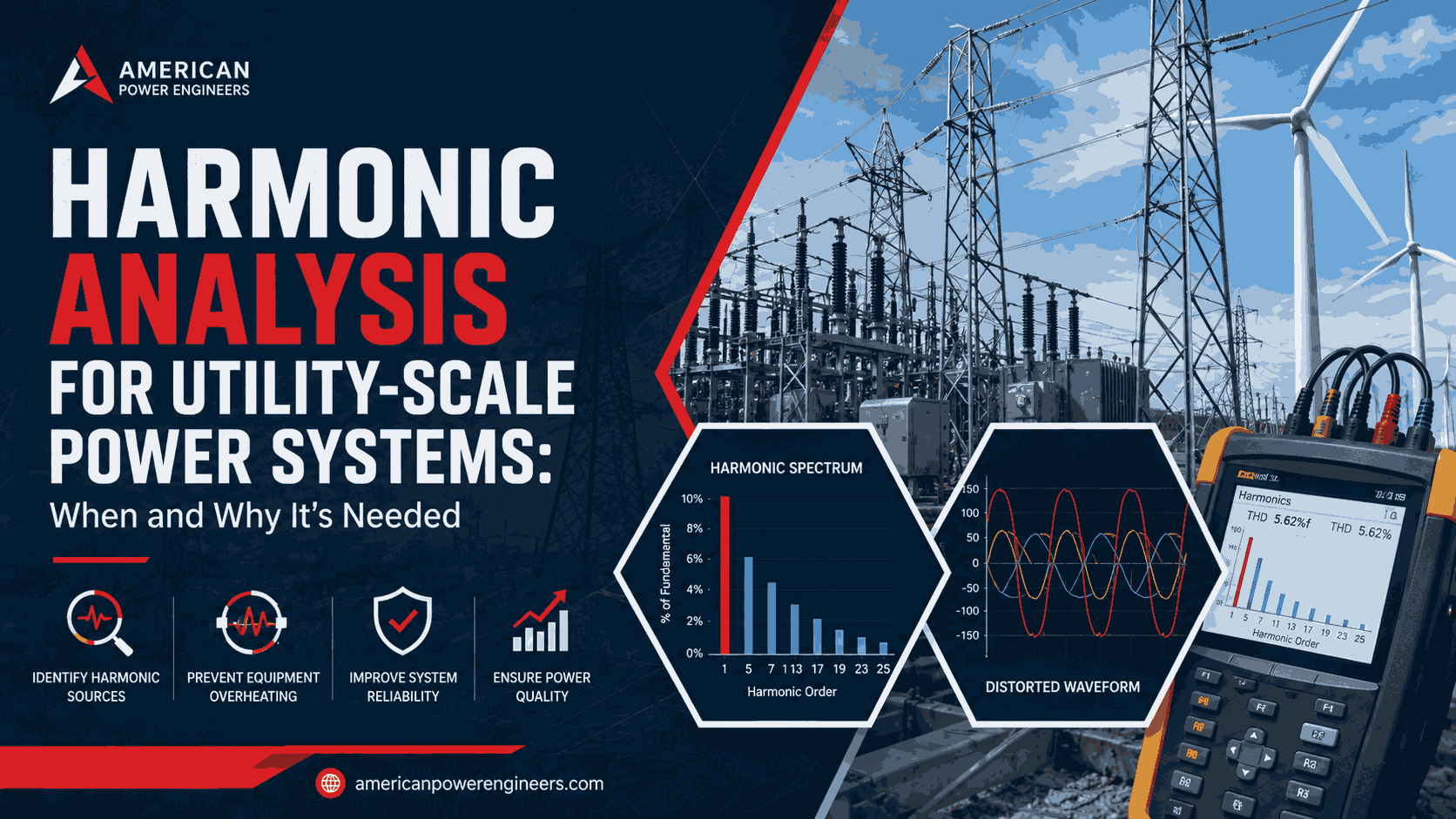
Harmonic analysis is the engineering study that quantifies distortion in the voltage and current waveforms of a power system, caused by non-linear loads and power-electronic devices such as inverters, variable frequency drives, and rectifiers.
Instead of a clean 60 Hz sine wave, these devices draw or inject current at multiples of the fundamental frequency the 3rd, 5th, 7th, 11th harmonics and so on distorting the waveform actually delivered to the grid.
Need Engineering Support for Your Power Project?
American Power Engineers delivers power system studies, substation design, renewable energy engineering, BESS projects, NERC compliance, MEP engineering, and POI interconnection services.
Explore Our Engineering ServicesThe study models these harmonic sources, calculates the resulting Total Harmonic Distortion (THD) and Total Demand Distortion (TDD) at key buses and checks system impedance for resonance conditions where harmonic currents can be amplified rather than damped.
Why Harmonic Analysis Matters for Utility-Scale Power Systems
Utility-scale solar, wind, and BESS plants are built almost entirely on power-electronic interfaces, inverters, converters, and switching devices that are inherently non-linear sources of harmonic current.
As renewable penetration on a feeder or transmission bus increases, the aggregate harmonic contribution from dozens or hundreds of inverters can be significant enough to violate utility limits even when every individual unit is well within its nameplate rating.
Left unaddressed, harmonic distortion causes real, measurable problems:
- Transformer and cable overheating from added RMS current and eddy current losses
- Capacitor bank failure from resonance amplification at specific harmonic frequencies
- Protective relay misoperation due to distorted current waveforms feeding relay algorithms
- Nuisance tripping of sensitive electronic loads and control equipment
- Interconnection application rejection or delay when utility screening studies flag non-compliance
- Metering and power factor billing inaccuracies at the point of common coupling
These aren’t hypothetical risks. Utility interconnection engineers and plant owners frequently report exactly this pattern in technical forums: harmonic limits that were only nominally checked at the design stage surface as compliance failures during commissioning field tests, forcing costly rework of filters or transformer configurations after equipment is already installed.
Catching resonance and distortion issues in the modeling stage rather than during field verification is the entire point of running the study early.
Planning a Solar, Wind, BESS, or Grid Interconnection Project?
Our engineering team helps project owners, developers, utilities, and facility teams move from technical planning to reliable project execution.
View Engineering ServicesWhen Is Harmonic Analysis Needed?
Harmonic analysis isn’t a blanket requirement for every project, but the following triggers make it a near-certainty in utility-scale work:
1. Utility-Scale Solar, Wind, or BESS Interconnection Nearly every transmission and distribution-connected renewable project is required to demonstrate harmonic compliance as part of its Large Generator Interconnection Agreement (LGIA) or equivalent.
This is one of the standard scope items our team addresses alongside load flow and short circuit studies, if you’re pursuing an ERCOT project specifically, see our ERCOT interconnection services for how harmonic and POI studies are scoped together for that region.
2. Any facility Adding Power-Electronic Loads or Sources Variable frequency drives, UPS systems, rectifiers, arc furnaces, and inverter-based generation all introduce harmonic current. Adding any of these to an existing system changes the harmonic profile and warrants a fresh study.
3. Capacitor Bank Installation or Power Factor Correction Capacitor banks change system impedance and can create resonance at specific frequencies, amplifying harmonics that were previously harmless. Any capacitor bank addition should be paired with a harmonic/resonance check.
4. High Renewable Penetration on a Feeder or Substation As aggregate inverter capacity on a bus grows, cumulative harmonic injection can exceed limits even if each individual plant is compliant — a common issue on feeders serving multiple solar or storage interconnections.
5. Documented Power Quality Complaints Equipment nuisance tripping, transformer overheating, or unexplained capacitor failures are classic symptoms worth investigating with a harmonic study before replacing hardware.
6. Utility or NERC-Driven Compliance Requirements Some interconnection agreements and reliability standards require periodic harmonic verification, particularly for larger inverter-based resources under IEEE 1547 and IEEE 2800.
IEEE 519: The Governing Standard
IEEE 519, Recommended Practice and Requirements for Harmonic Control in Electric Power Systems, is the standard most U.S. utilities reference for harmonic limits at the Point of Common Coupling (PCC). It sets two categories of limits:
- Voltage distortion limits, which are the utility’s responsibility to maintain on the delivered voltage
- Current distortion limits (TDD), which are the customer or generator’s responsibility, scaled based on the ratio of available short circuit current to maximum demand load current at the PCC
For inverter-based renewable generation, IEEE 1547-2018 and IEEE 2800-2022 layer additional current distortion requirements on top of IEEE 519 and most Large Generator Interconnection Agreements explicitly reference compliance with these standards as a condition of interconnection approval.
How a Harmonic Analysis Study Is Performed
Step 1: System Data Collection Single-line diagrams, transformer impedance data, cable and conductor parameters, capacitor bank ratings, and manufacturer harmonic injection spectra for inverters or other non-linear equipment.
Step 2: Harmonic Source Modeling Each non-linear device is modeled as a current source injecting harmonics at characteristic frequencies and magnitudes, based on manufacturer test data or IEEE-published spectra.
Step 3: Frequency Scan and Impedance Analysis The system model is scanned across a range of frequencies to identify resonance points where system impedance peaks the conditions most likely to amplify harmonic distortion to damaging levels.
Step 4: THD/TDD Calculation Voltage and current distortion at the PCC and key internal buses are calculated and compared against IEEE 519 limits for the applicable short circuit ratio.
Step 5: Mitigation Design (If Required) Where limits are exceeded, mitigation options are evaluated: harmonic filters (tuned or broadband), transformer connection changes (delta-wye configurations to cancel triplen harmonics), reactor additions to shift resonance points, or capacitor bank detuning.
Our power system studies team performs IEEE 519-aligned harmonic analysis as part of interconnection and facility engineering packages, working alongside the protective relay coordination and short circuit work needed to fully qualify a system for energization.
Avoiding the Most Common Harmonic Analysis Mistakes
- Waiting until commissioning to check compliance. Field-testing a plant that fails IEEE 519 after equipment is installed is far more expensive than modeling it during design.
- Modeling inverters as ideal current sources. Real inverter harmonic spectra vary with loading and should be based on actual manufacturer test data, not generic assumptions.
- Ignoring background distortion. The existing grid already carries some harmonic distortion; a study that only accounts for the new facility’s contribution can miss compliance failures caused by the combination of both.
- Overlooking resonance from capacitor banks added later. A system that passed its original study can fail after an unrelated capacitor bank installation changes system impedance.
FAQs
What is the difference between THD and TDD?
THD (Total Harmonic Distortion) expresses distortion as a percentage of the actual fundamental current or voltage at the time of measurement. TDD (Total Demand Distortion) expresses current distortion as a percentage of the maximum demand load current, which is the metric IEEE 519 actually uses for current limits making TDD less volatile during light-load conditions.
Does every solar or BESS project need a harmonic study before interconnection?
Most utilities and transmission operators require harmonic compliance documentation as part of the interconnection study process, particularly for transmission-connected projects. Even where it isn’t explicitly mandated, running the study protects against costly post-commissioning compliance failures.
Can harmonic distortion damage equipment even if THD is within limits?
Yes. Aggregate THD can be within limits while a specific resonant frequency amplifies a single harmonic order enough to damage a capacitor bank or overheat a transformer. This is why a frequency scan for resonance is a core part of the study, not just a THD calculation.
How is harmonic distortion mitigated once it’s identified?
Common mitigation approaches include tuned or broadband harmonic filters, transformer delta-wye reconfiguration, series reactors to shift resonance points away from problem frequencies, and capacitor bank detuning reactors.
Who is responsible for harmonic compliance the generator or the utility?
IEEE 519 splits responsibility: the utility is responsible for voltage distortion on the delivered supply, while the customer or generator is responsible for current distortion injected at the point of common coupling. Interconnection agreements typically hold the generator accountable for demonstrating current distortion compliance.
When in the project timeline should harmonic analysis be performed?
Ideally during the interconnection study and detailed design phase before equipment procurement so filter or transformer configuration decisions can be built into the design rather than retrofitted after a failed field test.
Harmonic distortion is one of the few power quality issues that’s genuinely cheaper to model than to fix in the field. If your project involves inverter-based generation, capacitor banks, or a pending interconnection application, running the study early protects both your commissioning schedule and your equipment.
Ready to scope a harmonic analysis for your project? Request a Proposal | Power System Studies | ERCOT Interconnection Services
Work With American Power Engineers
Expert engineering support for power system studies, substation design, renewable energy projects, BESS engineering, NERC compliance, MEP engineering, and POI interconnection services.
Explore All Engineering Services