
Protection Relay Testing: What Happens Before Plant Energisation?
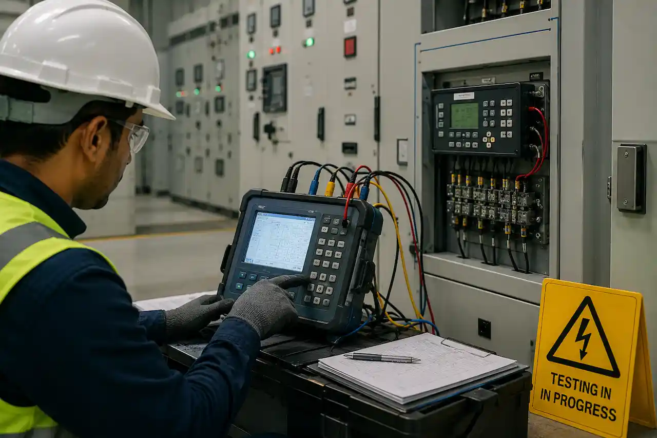
Before a power plant, solar farm, battery energy storage system, or other electrical facility is energised, its protection systems must be carefully inspected and tested. Protection relays play a critical role in keeping electrical equipment and the wider power system safe. They are designed to detect abnormal conditions and initiate the correct response, such as tripping a circuit breaker or isolating faulty equipment.
However, installing a protection relay and applying the correct settings is not enough. Before energisation, engineers need to confirm that the relay receives the correct electrical signals, processes those signals correctly, communicates with connected systems where required, and operates the appropriate trip circuits. This process is known as protection relay testing. Proper testing helps identify wiring errors, configuration issues, incorrect settings, communication problems, and trip circuit failures before the system becomes live. It is therefore one of the most important stages of electrical commissioning.
This guide explains what happens during protection relay testing, why it is required before plant energisation, and what project teams need to prepare.
What Is Protection Relay Testing?
Protection relay testing is the process of verifying that protection relays and associated circuits operate according to the approved protection design. A protection system continuously monitors electrical conditions such as current, voltage, frequency, and other system parameters. When it detects an abnormal condition, it must respond according to its configured protection logic.
Depending on the system, this response may involve:
- Tripping a circuit breaker
- Isolating a transformer or feeder
- Blocking specific equipment
- Sending an alarm
- Initiating a control action
Testing verifies that these actions occur correctly and under the intended conditions. The process can involve the relay itself, instrument transformers, wiring, trip circuits, circuit breakers, communication systems, and control interfaces. This is why protection relay testing should not be viewed as simply checking whether a relay turns on or off. The complete protection chain must be evaluated.
Need Engineering Support for Your Power Project?
American Power Engineers delivers power system studies, substation design, renewable energy engineering, BESS projects, NERC compliance, MEP engineering, and POI interconnection services.
Explore Our Engineering ServicesWhy Is Protection Relay Testing Important Before Energisation?
Once high-voltage equipment is energised, electrical faults can create serious risks for personnel and equipment. Protection systems must respond quickly and correctly when abnormal conditions occur. A relay that fails to operate when required can allow a fault to continue and potentially damage expensive electrical infrastructure.
At the same time, a protection relay that operates incorrectly can cause unnecessary outages and affect plant availability. Testing before energisation helps reduce both risks. The objective is to confirm that the protection system is ready before the plant enters service. A structured testing process can help identify:
- Incorrect relay configurations
- Wiring and termination errors
- Incorrect CT or VT connections
- Problems with trip circuits
- Communication issues
- Incorrect protection logic
- Circuit breaker control problems
Finding these issues before energisation is usually safer and easier than diagnosing them after the system is live.
Understanding the Protection System Before Testing
Before testing begins, engineers need to understand how the protection system has been designed. Protection schemes can vary significantly depending on the facility and equipment being protected. A solar plant, BESS facility, industrial power system, substation, or conventional generating plant may each have different protection requirements. The testing team normally reviews key project information before starting work.
This may include:
- Single-line diagrams
- Protection and control schematics
- Approved relay settings
- Logic diagrams
- Equipment datasheets
- Manufacturer manuals
- Communication architecture
- Cause and effect documentation
These documents help engineers understand what the protection system is expected to do. Without this preparation, testing can become inefficient because engineers may spend time identifying the intended design instead of verifying actual system performance.
Planning a Solar, Wind, BESS, or Grid Interconnection Project?
Our engineering team helps project owners, developers, utilities, and facility teams move from technical planning to reliable project execution.
View Engineering ServicesStage 1: Visual Inspection and Installation Checks
Protection relay testing often begins with a physical inspection. Before detailed tests are performed, engineers check whether protection panels, relays, wiring, and associated equipment have been installed correctly.
The inspection may include checking:
- Relay identification and labelling
- Panel condition
- Wiring terminations
- Circuit references
- Grounding arrangements
- Test switch positions
- Auxiliary power supplies
The purpose of this stage is to identify obvious installation issues before electrical testing begins. A missing termination or incorrectly labelled wire may appear to be a simple problem, but it can create significant confusion during functional testing. Visual inspections therefore provide an important foundation for the remaining commissioning activities.
Stage 2: Reviewing Protection Relay Settings
Protection relay settings define how the relay responds to different electrical conditions. These settings are typically developed based on the results of power system studies and the electrical characteristics of the system.
Before testing, engineers need to verify that the approved settings have been correctly applied to the relay. This process can involve comparing the relay configuration against the approved settings documentation. Important checks may include:
- Protection function enablement
- Pickup values
- Time delays
- Operating curves
- Logic configuration
- Communication settings
The goal is not simply to confirm that settings exist in the relay. Engineers must verify that the installed configuration matches the approved protection design. Configuration errors can occur when files are loaded incorrectly, changes are made during project development, or equipment is replaced with a different model. Verifying settings before functional testing helps prevent engineers from testing the wrong configuration.
Stage 3: Secondary Injection Testing
Secondary injection testing is commonly used to verify how a protection relay responds to simulated electrical conditions. During this test, controlled current or voltage signals are injected directly into the relay. The test equipment simulates conditions that the relay would normally receive from current transformers or voltage transformers. Engineers can then verify whether the relay operates at the correct pickup value and within the expected time. Secondary injection testing may be used to check functions such as:
- Overcurrent protection
- Overvoltage protection
- Undervoltage protection
- Frequency protection
- Differential protection
- Other configured protection elements
The exact tests depend on the relay and protection scheme. This stage helps confirm that the relay logic and settings operate correctly before the relay receives signals from the actual electrical system.
Stage 4: Checking CT and VT Circuits
Current transformers, commonly known as CTs, and voltage transformers, commonly known as VTs, provide critical measurement signals to protection relays. If these circuits are incorrectly connected, the relay may receive inaccurate information. Problems with CT or VT circuits can affect the direction, magnitude, or phase relationship of the electrical signals seen by the relay. Testing may therefore include verification of:
- CT polarity
- CT ratios
- VT ratios
- Wiring connections
- Phase identification
- Circuit continuity
These checks are particularly important because an incorrectly connected measurement circuit may cause a protection scheme to behave in an unexpected way. The relay itself may be correctly configured, but incorrect field wiring can still prevent the protection system from operating as designed.
Stage 5: Trip Circuit Testing
A protection relay must be able to do more than detect a fault. When required, it must send the correct signal through the trip circuit and cause the appropriate circuit breaker or switching device to operate. Trip circuit testing verifies this part of the protection chain. The test may involve checking the relay output contacts, trip wiring, auxiliary relays, and circuit breaker trip mechanisms. Engineers need to confirm that the correct protection function produces the correct response.
For example, a protection operation intended to isolate a particular feeder should not trip unrelated equipment.
Trip circuit testing helps identify problems such as:
- Incorrect wiring
- Failed output contacts
- Faulty auxiliary relays
- Circuit breaker control problems
- Incorrect trip logic
This is one of the most important stages before energisation because it verifies the connection between fault detection and the physical response of the electrical system. For facilities involving complex substations and high-voltage equipment, these protection interfaces must also align with the wider requirements of substation design engineering.
Stage 6: Functional Logic Testing
Modern protection systems often include complex logic. A relay may need to receive information from other equipment, check specific conditions, and then determine whether a trip should occur.
For example, certain protection functions may be blocked during specific operating conditions. Other functions may require signals from multiple devices before initiating an action.
Functional logic testing verifies that these sequences work correctly. Engineers may simulate different operating conditions and confirm the expected response. The testing process may check:
- Permissive signals
- Blocking logic
- Interlocking
- Breaker failure schemes
- Alarm functions
- Trip logic
The objective is to confirm that the protection system responds correctly as a complete logic scheme rather than as individual functions operating in isolation.
Stage 7: Communication and SCADA Testing
Many modern protection relays communicate with SCADA systems, plant controllers, or other intelligent electronic devices. Reliable communication and control integration are also important during grid interconnection engineering, where protection systems and plant controls must coordinate with the requirements of the connected power network.
Communication testing verifies that required information is exchanged correctly. This may include equipment status, alarms, measurements, protection events, and control signals.
However, confirming that a relay is connected to the network is not enough. The testing team should verify that the correct information is transmitted and displayed accurately.
Typical checks may include:
- Communication status
- Data point mapping
- Alarm indications
- Event records
- Measurements
- Time synchronisation
Communication problems can create operational challenges even when the protection functions themselves are working correctly. For example, a relay may trip properly during a fault, but the control room may receive an incorrect status or fail to receive an alarm.
End-to-end testing helps identify these issues before the plant enters normal operation.
Stage 8: Interlock and Control Testing
Protection systems often interact with circuit breakers, disconnect switches, plant controls, and other electrical equipment. Interlocks are used to prevent unsafe or incorrect operations. During commissioning, engineers test these interlocks to confirm that equipment responds correctly under different conditions.
For example, a circuit breaker may be prevented from closing when a specific safety condition has not been met.
Testing verifies both sides of the requirement:
- The equipment should operate when the correct conditions are met.
- The equipment should remain blocked when required conditions are not met.
This helps prevent unexpected equipment operations after energisation.
Stage 9: End-to-End Protection Testing
Individual relay testing is important, but it does not always confirm that the complete protection scheme works correctly. End-to-end testing evaluates the full path from the simulated fault condition through the protection system to the final response. Depending on the project, this may involve multiple relays and devices communicating with each other. The objective is to verify that:
- The correct abnormal condition is detected.
- The protection logic responds correctly.
- Required communication signals are exchanged.
- The correct trip command is issued.
- The intended circuit breaker operates.
- Other systems receive the correct status and alarms.
This type of testing is particularly valuable for complex protection schemes where multiple devices must coordinate their operation.
Common Problems Found During Protection Relay Testing
Protection testing often identifies issues that are not visible during installation. Finding these problems before energisation is one of the main reasons the commissioning process is so important.
- Incorrect Relay Settings: The relay may contain settings that do not match the latest approved protection study. This can happen when project changes are made but updated settings are not applied to the equipment.
- Wiring Errors: Incorrect or incomplete wiring can affect measurements, trip signals, and control functions. Even a small termination error can cause significant problems during functional testing.
- CT and VT Configuration Issues: Incorrect polarity, ratios, or phase connections can cause protection relays to receive incorrect electrical information. These issues can affect the performance of multiple protection functions.
- Logic and Interlock Problems: Modern protection systems can contain complex logic involving multiple conditions and devices. Configuration errors may only become visible when complete functional sequences are tested.
- Communication Issues: Incorrect network settings or data mapping can prevent protection information from reaching the SCADA system or other connected devices.
How to Avoid Protection Testing Delays
Protection testing delays can affect the overall commissioning and energisation schedule. One of the most effective ways to reduce these delays is to ensure that the protection design and documentation are complete before testing begins. The testing team should have access to the latest approved settings, drawings, and logic documentation. Clear coordination between engineering, construction, and commissioning teams is also essential.
Project teams should confirm that panels are physically complete and that wiring is ready before specialist protection engineers arrive on site. A structured readiness process can help verify key requirements, including:
- Protection panels are installed
- Required wiring is complete
- Approved settings are available
- Auxiliary supplies are operational
- Circuit breakers are ready for testing
- Required communication networks are available
Testing should also be planned as a sequence rather than as a single final activity. Early checks can identify installation and configuration issues before they affect critical energisation milestones.
The Role of Specialist Protection Engineers
Protection systems are highly technical and directly connected to electrical safety and system reliability. Specialist protection engineers understand how protection functions, relay settings, measurement circuits, trip logic, and system coordination work together. Their role during commissioning goes beyond operating test equipment. They analyse whether the protection system is behaving according to the approved engineering design.
When problems are identified, specialist engineers help investigate issues such as:
- Relay configuration errors
- Field wiring problems
- Incorrect CT connections
- Communication faults
- Circuit breaker control issues
A failed test may not immediately reveal the root cause, which is why these problems need to be investigated systematically. Their expertise is particularly valuable before energisation because unresolved protection issues can prevent the project from safely moving into the next commissioning stage.
What Happens After Protection Relay Testing?
Once the required protection tests have been completed, the project team reviews the results and resolves any outstanding issues. Test records are documented, and critical findings must be addressed before the relevant equipment is energised. Protection testing is then coordinated with other commissioning activities, including electrical equipment testing, SCADA verification, control testing, and energisation readiness reviews. This broader process often requires specialist owner’s technical advisory services to help project stakeholders manage technical requirements and critical project milestones.
The goal is to confirm that all critical systems are ready to operate together. Successful protection relay testing does not simply mean that every relay has passed an individual test.
It means the protection system has demonstrated that it can detect abnormal conditions and initiate the correct response within the wider electrical system.
Need Support with Protection Relay Testing?
Protection relay testing is a critical part of commissioning and energisation readiness. It requires a detailed understanding of protection settings, relay logic, measurement circuits, trip systems, communication networks, and electrical equipment.
Grid Engineering Group supports renewable energy and power system projects through specialist power systems engineering, protection and relay testing, commissioning, power system studies, SCADA integration, and grid interconnection support.
Whether your project is preparing for energisation or experiencing issues during protection testing, specialist engineering support can help identify problems and improve coordination across the commissioning process.
Contact Grid Engineering Group to discuss your protection relay testing and commissioning requirements.
Frequently Asked Questions
What is protection relay testing?
Protection relay testing verifies that protection relays and associated circuits detect abnormal electrical conditions and initiate the correct response.
Why is protection relay testing required before energisation?
Testing helps identify configuration, wiring, logic, and trip circuit issues before high-voltage equipment becomes live.
What is secondary injection testing?
Secondary injection testing uses controlled current or voltage signals to simulate electrical conditions and verify how a protection relay responds.
What is trip circuit testing?
Trip circuit testing verifies that a protection relay can send the correct trip signal and that the associated circuit breaker or switching device responds correctly.
What is end-to-end protection testing?
End-to-end testing verifies the complete protection chain, from a simulated fault condition through relay logic and communication systems to the final circuit breaker operation.
Who performs protection relay testing?
Protection relay testing is typically performed by qualified commissioning and protection engineers with experience in electrical protection systems and the relevant testing procedures.
Work With American Power Engineers
Expert engineering support for power system studies, substation design, renewable energy projects, BESS engineering, NERC compliance, MEP engineering, and POI interconnection services.
Explore All Engineering Services