
Relay Coordination Study: Ensuring Protection Systems Work Together
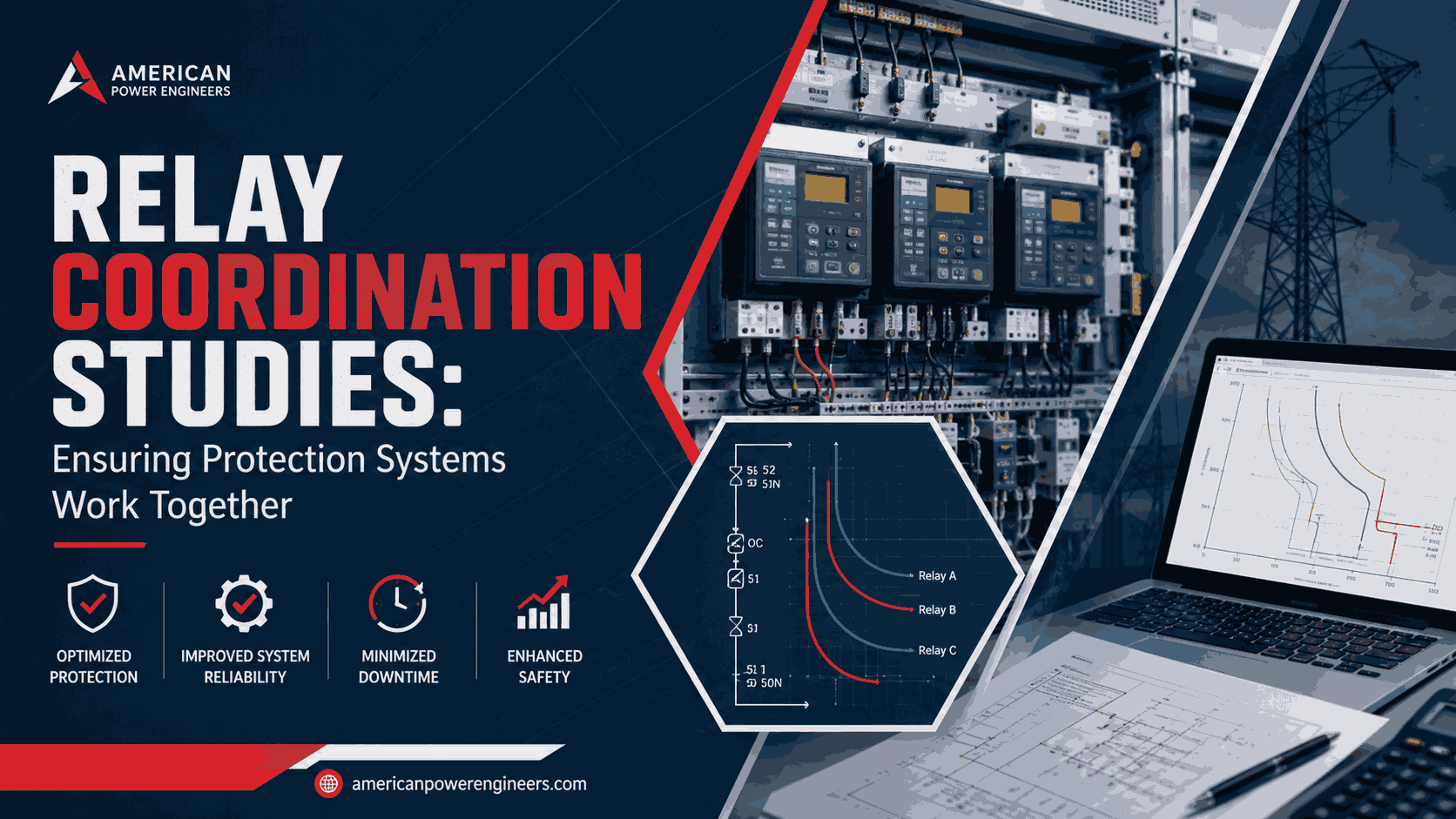
When a fault occurs on a power system, dozens of protective relays may sense it at once. Only one of them should travel. A relay coordination study is the engineering analysis that makes sure the right relay operates first, the right breaker opens, and every other device stands down so a single fault clears a single section of the system instead of taking down an entire substation, feeder, or plant.
Without this coordination, systems experience two opposite but equally costly failures: relays that trip when they shouldn’t (nuisance tripping), and relays that fail to trip fast enough when they should (delayed clearing, equipment damage, and safety hazards). Both problems show up constantly in field reports and troubleshooting forums: a breaker trips with “no apparent fault,” or an upstream device opens before the local one gets a chance to clear a downstream fault.
Almost every one of these cases traces back to the same root cause: relay settings that were never properly coordinated, or that drifted out of coordination as the system changed.
This guide breaks down what a relay coordination study actually involves, the real-world problems it solves, and how to know when your system needs one.
What Is a Relay Coordination Study?
A relay coordination study analyzes the time-current characteristics of every protective device in a system relays, fuses, and circuit breakers to confirm they operate in the correct sequence during a fault. The goal is selectivity: the protective device closest to the fault clears it, while every upstream and adjacent device remains in service.
Need Engineering Support for Your Power Project?
American Power Engineers delivers power system studies, substation design, renewable energy engineering, BESS projects, NERC compliance, MEP engineering, and POI interconnection services.
Explore Our Engineering ServicesThe study typically produces:
- Time-current curves (TCCs) showing how each device’s operating time changes with fault current magnitude
- Coordination time intervals (CTIs) between primary and backup devices, typically 0.2–0.4 seconds, to prevent simultaneous tripping
- Relay setting recommendations for pickup current, time dial, and instantaneous elements
- Fault current data at every bus, pulled from a short circuit study, since coordination cannot be done without knowing available fault current at each point in the system
Relay coordination doesn’t happen in isolation it depends directly on accurate short circuit and load flow data, which is why it’s normally scoped as part of a broader power system studies engagement rather than a standalone exercise.
The Real Problems Poor Coordination Creates
Engineers troubleshooting “mystery trips” and forum threads on relay behavior consistently point back to a handful of recurring failure patterns. If you recognize any of these on your system, it’s a strong signal that a coordination study or a re-study is overdue.
Nuisance tripping
Pickup settings that are too sensitive cause relays to trip on motor starting inrush, transformer energization, or normal load fluctuations events that look like faults to an under-coordinated relay but aren’t. This is one of the most commonly reported protection complaints in the field, and it’s almost always a settings problem, not a hardware problem.
Miscoordination and cascading outages
When time-current curves overlap between adjacent devices, an upstream breaker can open before the downstream device clears a local fault. Instead of losing one feeder, you lose an entire bus or substation. This is the exact failure mode a coordination study is designed to prevent.
Settings that drift out of coordination as the system changes
system that was coordinated correctly at commissioning doesn’t stay coordinated forever. Adding a solar, wind, or BESS interconnection changes fault current contribution and can shift the entire coordination picture a scenario that’s become increasingly common as more generation connects to distribution and transmission systems.
Planning a Solar, Wind, BESS, or Grid Interconnection Project?
Our engineering team helps project owners, developers, utilities, and facility teams move from technical planning to reliable project execution.
View Engineering ServicesIf your system has added any new generation, load, or equipment since the original study, your settings need to be re-verified.
CT saturation and instrumentation errors
Undersized or improperly rated current transformers can distort the current signal a relay sees during high-magnitude faults, causing relays to misjudge fault current and trip incorrectly a problem that looks like a coordination issue but is actually rooted in CT sizing.
Backup protection gaps
If primary protection fails to operate a stuck breaker, a failed trip coil backup protection needs to pick up the fault within an acceptable time. Systems without a properly studied backup scheme can leave a fault uncleared far longer than acceptable, which raises incident energy levels and safety risk.
This is also why relay coordination studies and arc flash analysis are closely linked protective device clearing time is a direct input into every incident energy calculation.
How a Relay Coordination Study Is Performed
Step 1: Gather system data. This includes one-line diagrams, transformer nameplate data, cable and conductor impedances, CT/PT ratios, existing relay models and settings, and generation data (including any interconnected renewables or BESS).
Step 2: Run the short circuit study. Available fault current at every bus — for both maximum and minimum fault conditions — is required before any coordination work can begin.
Step 3: Build time-current curves for every device. Each relay, fuse, and breaker is plotted on a common TCC graph so overlaps and gaps become visible.
Step 4: Apply coordination margins. Standard coordination time intervals (typically 0.2–0.4 seconds between devices) are applied to prevent simultaneous or out-of-sequence tripping.
Step 5: Recommend and verify settings. Pickup, time dial, and instantaneous settings are calculated for every device, then cross-checked against equipment thermal withstand limits and NERC/IEEE requirements where applicable.
Step 6: Document and implement. Final settings are issued in a coordination report with TCC plots, and physically applied to relays in the field — ideally verified with as-left settings testing.
This process ties directly into equipment layout and protection zone design, which is why coordination is typically reviewed alongside substation design work rather than treated as a purely paper exercise.
When You Need a Relay Coordination Study (or a Re-Study)
- You’re commissioning a new substation, industrial facility, or generation interconnection
- You’ve added solar, wind, or BESS capacity even at a neighboring point of interconnection, which can change fault current contribution across the network
- You’re experiencing unexplained nuisance trips or breakers opening without a corresponding downstream fault
- Your last coordination study is more than 3–5 years old, or predates a system expansion
- You’re preparing for a NERC compliance audit and need to demonstrate documented protection coordination
- You’re pursuing interconnection approval and the transmission or distribution owner requires a coordination study as part of the interconnection agreement — for example, projects interconnecting into ERCOT, where the ERCOT Protocols require detailed protection coordination documentation as part of the interconnection process; see our ERCOT interconnection services for what that process typically involves
FAQs
What is the difference between a relay coordination study and a short circuit study?
A short circuit study calculates available fault current at every point in the system. A relay coordination study uses that fault current data to determine the correct relay settings and confirm devices operate in the right sequence. You cannot accurately coordinate relays without first completing a short circuit study — the two are sequential, not interchangeable.
How often should relay coordination studies be updated?
Most facilities should re-verify coordination every 3–5 years, or immediately after any change that affects fault current or system topology — new generation, new transformers, feeder reconfiguration, or load growth. Systems with interconnected renewables or BESS should be reviewed more frequently, since fault contribution from inverter-based resources can behave differently than traditional synchronous generation.
What causes relays to fall out of coordination over time?
The most common causes are system changes that weren’t followed by a settings review: new interconnected generation, transformer replacements with different impedance, network reconfiguration, or CT/PT changes. Coordination is a snapshot based on the system as it existed at study time — it doesn’t automatically adjust as the system evolves.
Can poor relay coordination cause a full blackout?
Yes. Miscoordination is a documented contributing factor in cascading outage events, where an upstream device trips before the local fault is cleared, removing far more of the system from service than the fault itself required. This is one of the primary reasons coordination studies are treated as a reliability requirement, not just a design nicety.
Does a relay coordination study affect arc flash incident energy?
Directly. Incident energy calculations under IEEE 1584 depend heavily on protective device clearing time. Faster, correctly coordinated clearing reduces incident energy and can lower required PPE category; slow or miscoordinated clearing increases it. This is why coordination studies and arc flash studies are usually performed together, or at minimum, in the same order — coordination first, arc flash second.
Who typically requires a relay coordination study?
Utilities and transmission owners generally require a documented coordination study as part of interconnection approval for new generation or major load additions. NERC-registered entities may also need coordination documentation to demonstrate compliance with applicable Protection and Control standards during an audit.
Our power system studies team performs relay coordination studies alongside short circuit, arc flash, and load flow analysis, so your protection settings are backed by a complete, standards-based picture of your system not just an isolated TCC plot.
Work With American Power Engineers
Expert engineering support for power system studies, substation design, renewable energy projects, BESS engineering, NERC compliance, MEP engineering, and POI interconnection services.
Explore All Engineering Services